Piano VFX Manual
First of all, thank you for using Piano VFX! I hope that I have simplified the process of making piano cover videos with visual effects. If you have any problems, feel free to contact me by email:
pianovfx@gmail.com
You can download Piano VFX here.
I would like to give credit to the libraries that I used in my application. For MIDI device handling and for MIDI recording I used DryWetMIDI, for file browsing I used UnityStandaloneFileBrowser, video rendering was possible thanks to NatCorder. Everything is put together in Unity.
I'm going to explain all of the features that Piano VFX has using these example files.
Using MIDI File
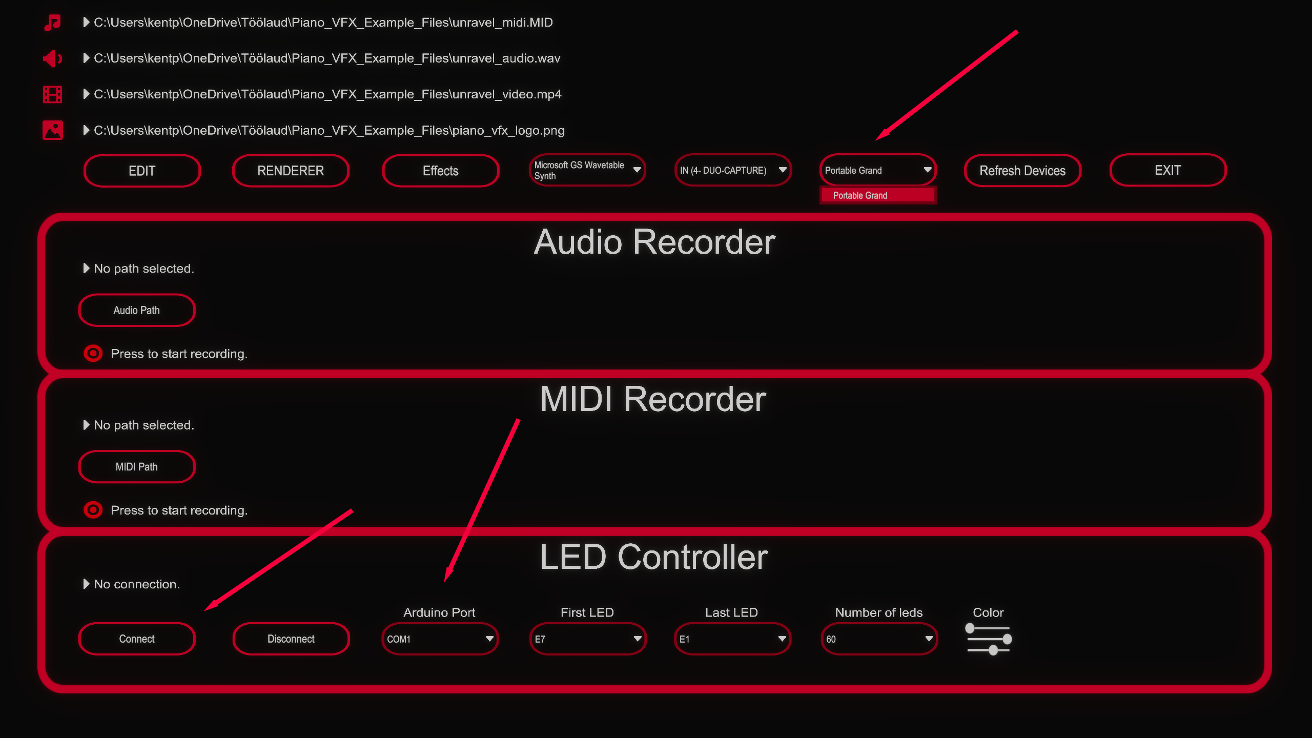
First we need to import a MIDI file. You can import your MIDI file under Media menu by pressing the note-shaped button.
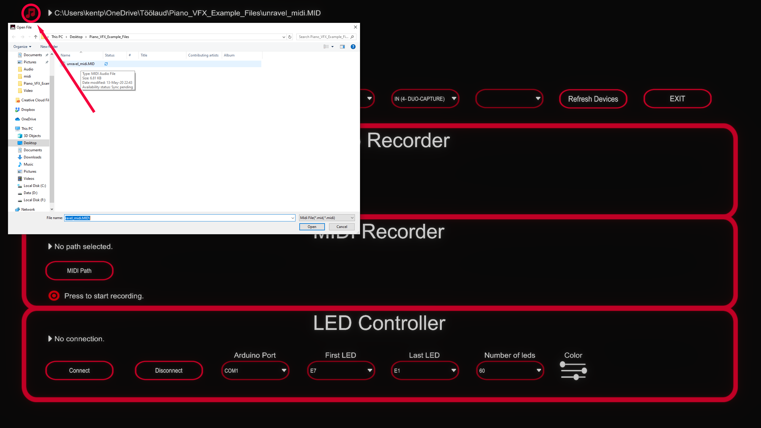
In simple terms, a MIDI file contains info about played notes, it doesn't have any audio data. Therefore we need a device that is able to generate the audio based on MIDI events. We can select our MIDI output device here:

You can use your digital piano as an output device by connecting it via USB cable. If you don't see your piano under the output devices, hit Refresh Devices.
Now we should be able to see and hear the notes in the selected MIDI file. To test that, we need to click on the Edit button.

Using Audio File
If you want to render your video with audio, you need to select an audio file(.wav or .ogg).

Now that the audio file is imported, we have to enable it. Under Edit menu there is a button called Audio, clicking it will open all of the audio editing tools, there, we can see and check Use audio file checkbox.
You should hear your selected audio file, but it probably isn't synchronized with the midi file. My recorded audio file is starting to play about 4.2 seconds too soon, so I have offsetted the audio back by 4.23 seconds.

If your audio file contains unwanted parts, you can remove them with trimming tools.
Using Video File
With Piano VFX it's possible to create Rousseau styled videos. To do that, we need to import a video file.

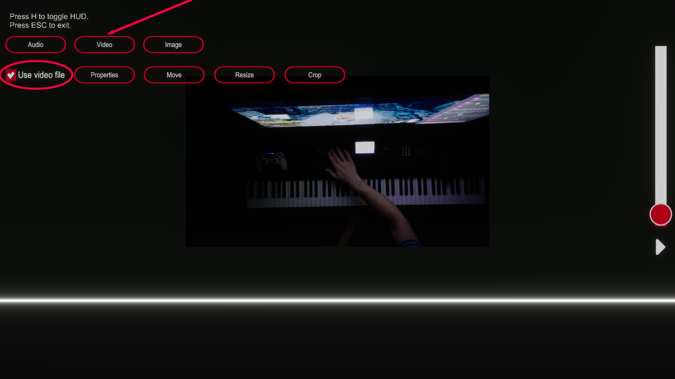
Let's enable our video. Under Edit menu we need to click the Video button and check the Use video file checkbox.
Under Properties we can change video Offset, Brightness, Rotation and Midi Y position.
My video is about 1.1 second behind my MIDI file, so I have set the Offset value to 1.13s.
I also adjusted the video brightness and rotation because my piano keyboard in the video is a bit tilted.
I going to adjust the Midi Y position as well, then there will be more room for my hands on the bottom of the video.

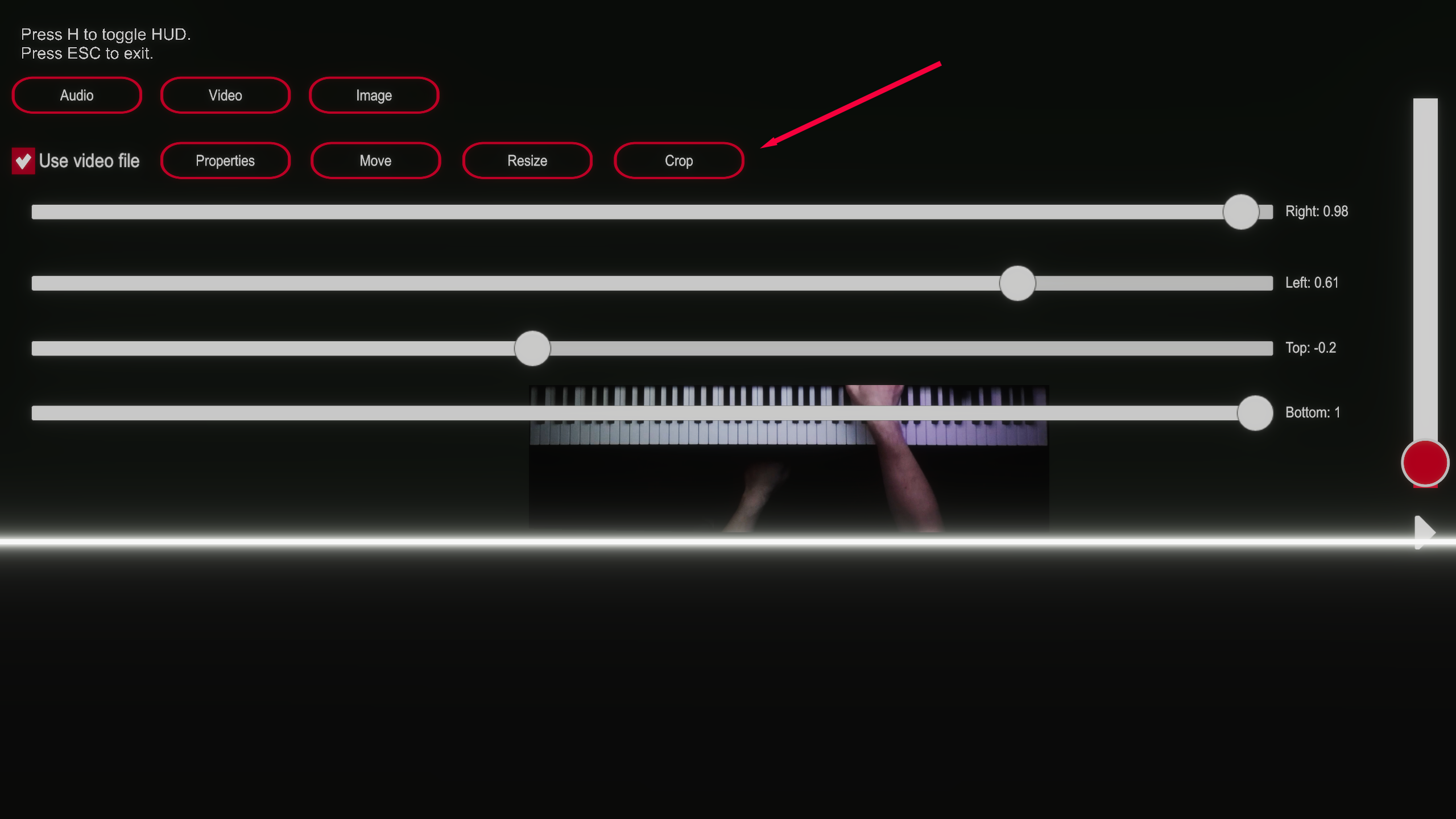
We only want the keyboard and the hands on the video, so let's Crop everything else out.
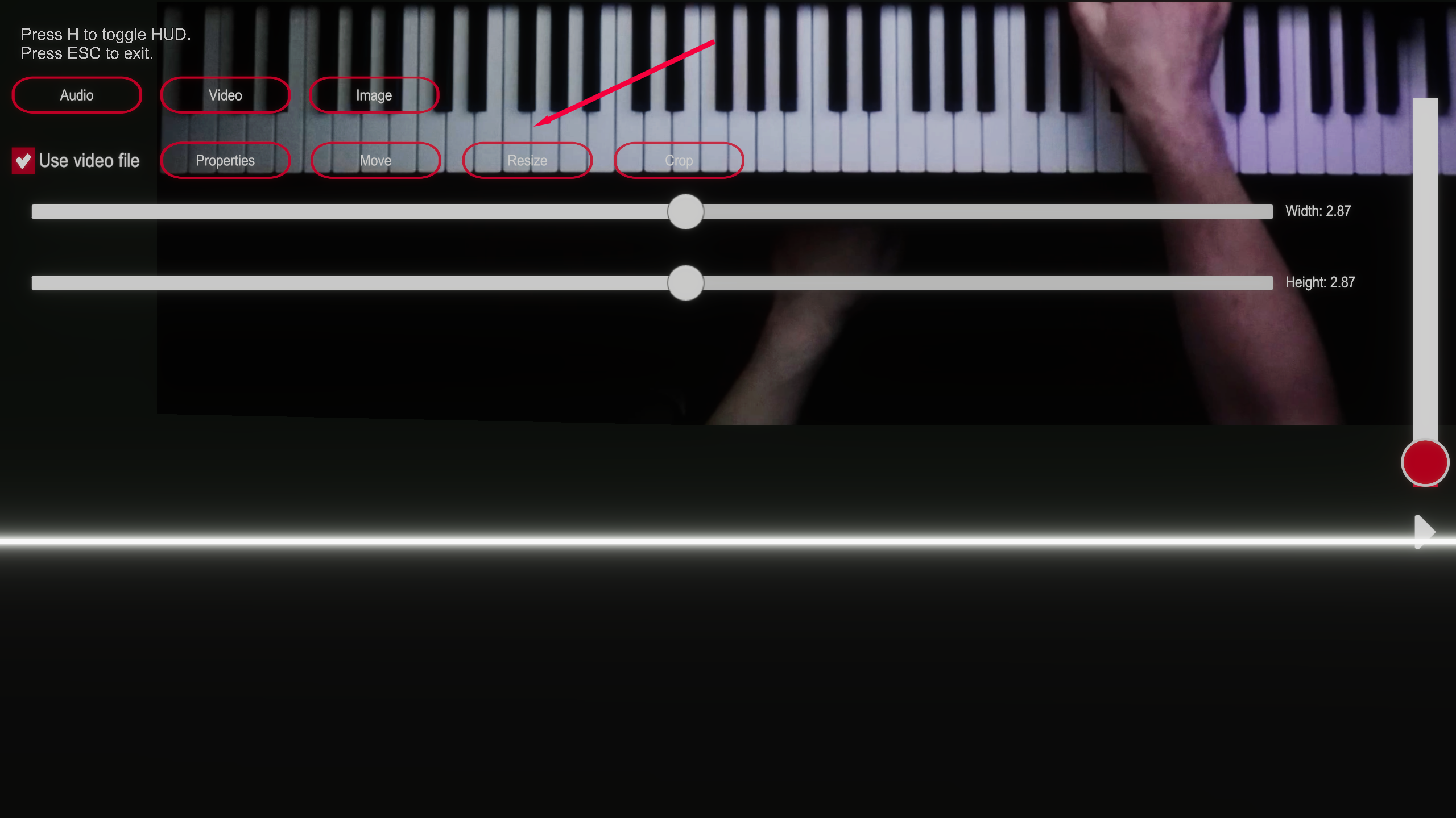
Let's change the size of the video with Resize tool and place at the bottom of the screen with Move tool.

Using Image File
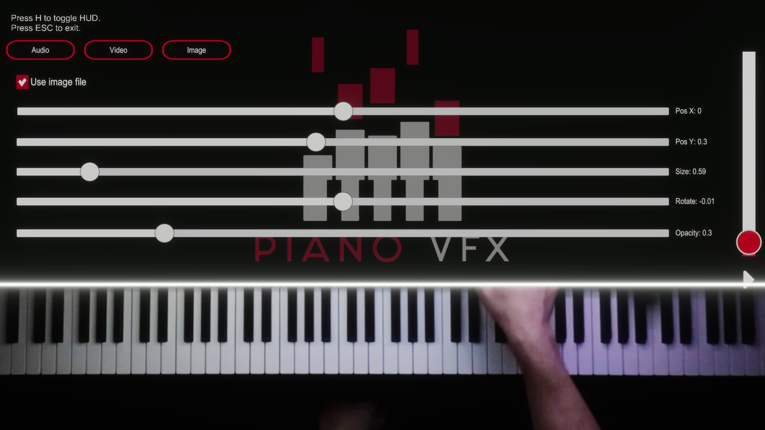
You can add an image to your video. I'm going to add Piano VFX logo.

Under Edit menu by clicking Image, we can adjust image Position, Size, Rotation and Opacity. I have chosen these values:
Customising Effects
Basically, our video is ready to be rendered, but there are no effects and everything is white. Let's change that under the Effect menu.
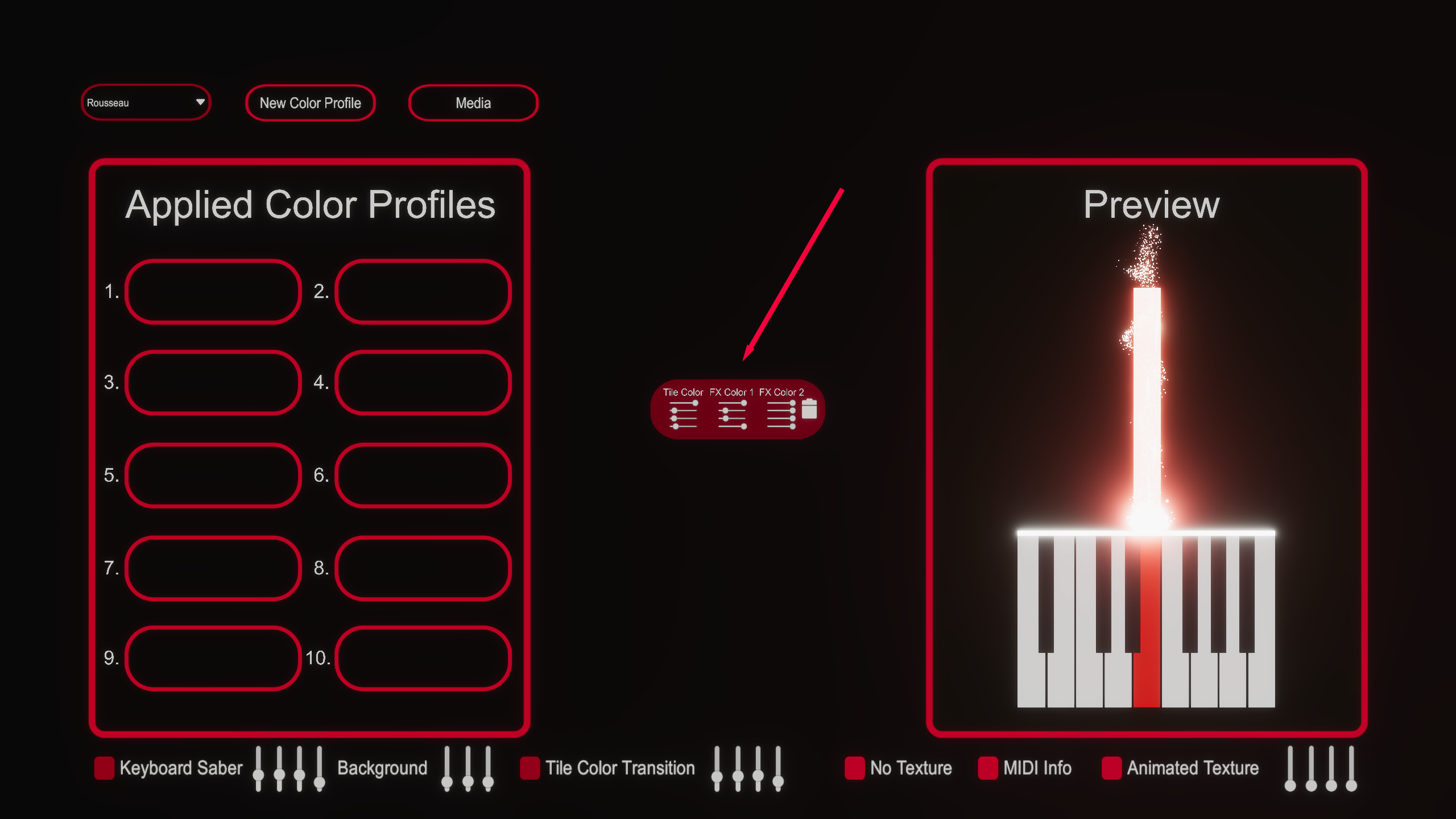
First choose your particle effect (I'm going to use Rousseau effects) and click the button called New Color Profile.

Now you should see a new Color Profile in the middle of the screen. First four sliders will change tile RGB value and Glow amount. Next sliders will change RGB values and Glow amount of the Particle Effect.
My Color Profile looks like this:
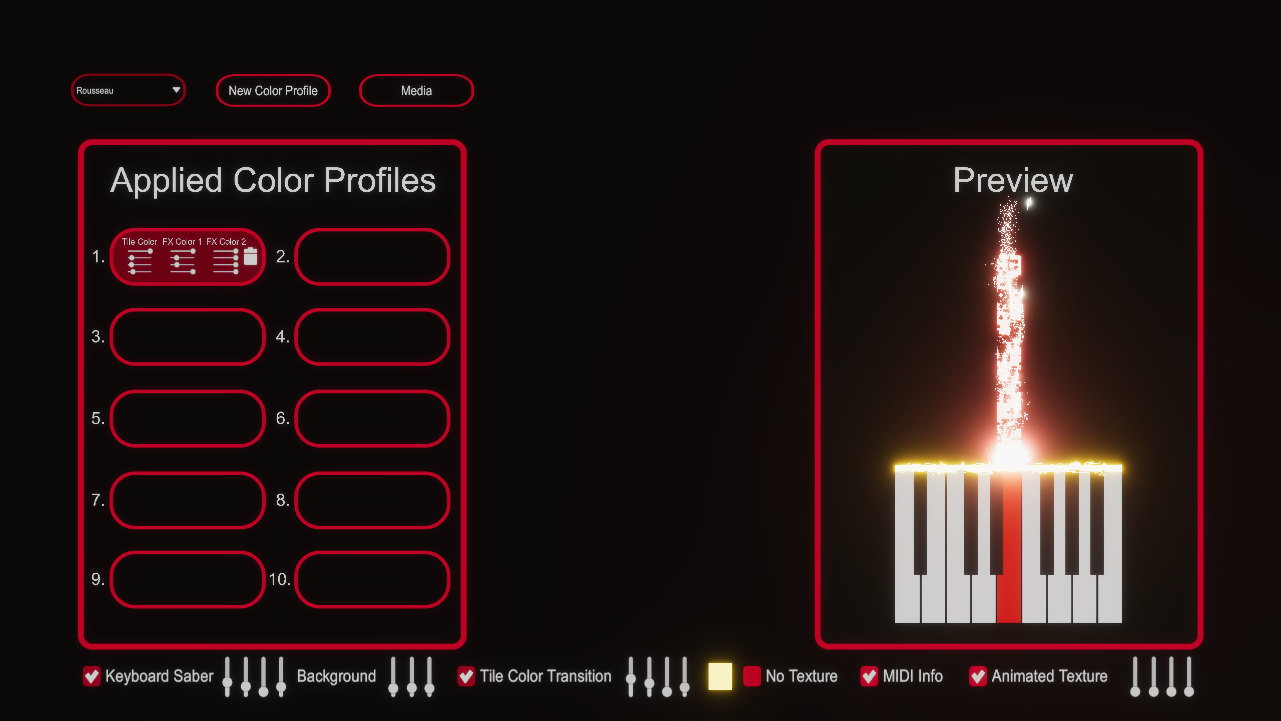
Now we have to apply the Color Profile. Click on the Color Profile with your right mouse button and drag it in the first slot. If your MIDI file has more than one track, you can create another Color Profile and drag it in one of the other slots.
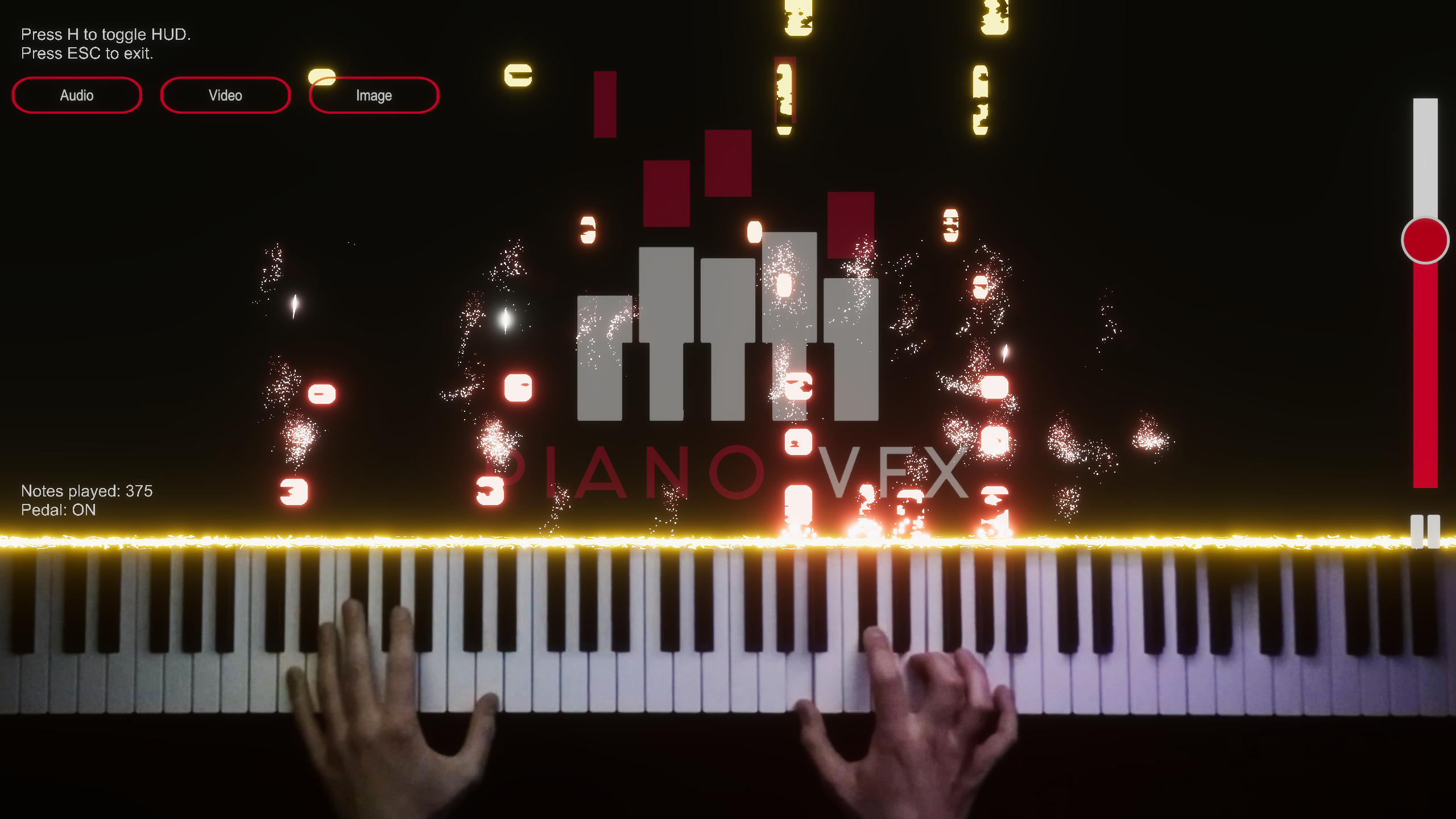
I'm going to check four checkboxes called Keyboard Saber, Tile Color Transition, MIDI Info and Animated Texture.
Keyboard saber animates the white line above the keyboard. Next to Keyboard Saber checkbox you can change its color and glow.
Tile Color Transition will change the tile color over lifetime. Next to Tile Color Transition checkbox you can change the spawn color of the tiles, they will gradually change from that color to their Color Profile color.
MIDI Info will display how many notes have been played and whether the pedal is ON or OFF.
Animated Texture adds moving noise texture to the tiles.
My Effect settings:
Now under Edit menu, we can see our effects and colors in action.
Rendering
Now it's time to render! Let's open the Renderer menu.
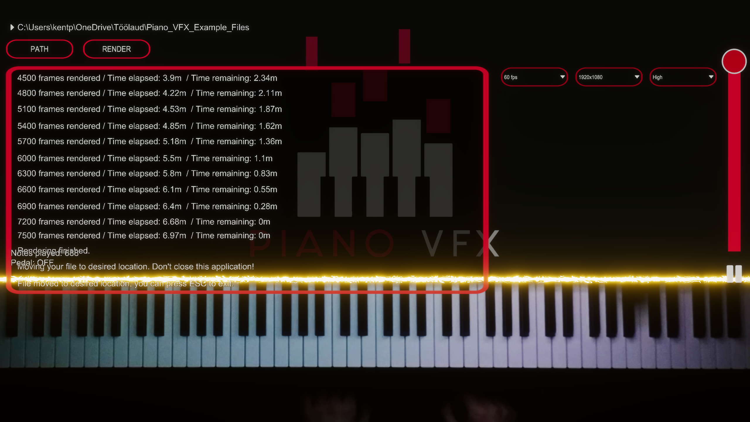
First thing we need to do, is choose a path for the video. On the right you can choose video Frame Rate, Resolution and Quality.

Click Render and wait, you can see that it took me seven minutes to render.
Here is the rendered video:
*This video is compressed by YouTube and looks much worse than the original file.
Audio Recording
Before you can record audio you have to choose a audio-in device and file path. After that, press the record button. Press record button again to stop recording.

*If you don't see your audio-in device, hit Refresh Devices.
MIDI Recording
Before you can record MIDI you have to choose a MIDI-in device and file path. After that, press the record button. Press record button again to stop recording.

*If you don't see your MIDI-in device, hit Refresh Devices.
LED Controller
LED controlling is a bit difficult and you probably need a little bit of knowledge about Arduino devices.
Roy Sukrit has made a very detailed tutorial on how to use the LED controller feature:
- HOW TO MAKE PIANO LED VISUALIZER - PART 1 (WORKFLOW)
- HOW TO MAKE PIANO LED VISUALIZER - PART 2 (COMPLETING SETUP)
- Arduino-LED-Piano (GitHub)
- Discord Server
To control LED strip, you need Arduino board and an adressable LED strip. I'm using Arduino UNO and WS2812B LED strip.
You need to program your Arduino board, for that you need Arduino IDE.
The LED strip should be powered using a 5V power source. At 5V, each LED draws about 50mA, when set to its full brightness. You should use external power source and around 330 Ohm resistor between the Arduino and the LED strip data pin, but for quick testing you can connect the LED strip like this:

Now you need to download the FastLED library. Click Clone or download -> Download ZIP. Extract the ZIP file and rename the folder above the files to FastLED. Now copy the FastLED folder to Documents/Arduino/libraries. It's time to connect you Arduino and open the Arduino IDE. Under Tools select Board: + "your Arduino board" and Port: "your Arduino port". Paste this code to Arduino IDE:
// https://github.com/FastLED/FastLED
#include <FastLED.h>
#define NUM_LEDS 60 // how many leds do you want to control
#define DATA_PIN 5 // your LED strip data pin
//#define CLOCK_PIN 13 // for SPI based LED strip you need to define CLOCK_PIN

int redVal = 255;
int greenVal = 255;
int blueVal = 255;
bool setColors = false;
bool receiveNotes = false;
int colorSetCounter = 0;

CRGB leds[NUM_LEDS];

void setup() {
    Serial.begin(9600);
    Serial.setTimeout(10);
    // Uncomment/edit one of the following lines for your leds arrangement.
    // ## Clockless types ##
    FastLED.addLeds<NEOPIXEL, DATA_PIN>(leds, NUM_LEDS);  // GRB ordering is assumed
    // FastLED.addLeds<SM16703, DATA_PIN, RGB>(leds, NUM_LEDS);
    // FastLED.addLeds<TM1829, DATA_PIN, RGB>(leds, NUM_LEDS);
    // FastLED.addLeds<TM1812, DATA_PIN, RGB>(leds, NUM_LEDS);
    // FastLED.addLeds<TM1809, DATA_PIN, RGB>(leds, NUM_LEDS);
    // FastLED.addLeds<TM1804, DATA_PIN, RGB>(leds, NUM_LEDS);
    // FastLED.addLeds<TM1803, DATA_PIN, RGB>(leds, NUM_LEDS);
    // FastLED.addLeds<UCS1903, DATA_PIN, RGB>(leds, NUM_LEDS);
    // FastLED.addLeds<UCS1903B, DATA_PIN, RGB>(leds, NUM_LEDS);
    // FastLED.addLeds<UCS1904, DATA_PIN, RGB>(leds, NUM_LEDS);
    // FastLED.addLeds<UCS2903, DATA_PIN, RGB>(leds, NUM_LEDS);
    // FastLED.addLeds<WS2812, DATA_PIN, RGB>(leds, NUM_LEDS);  // GRB ordering is typical
    // FastLED.addLeds<WS2852, DATA_PIN, RGB>(leds, NUM_LEDS);  // GRB ordering is typical
    // FastLED.addLeds<WS2812B, DATA_PIN, RGB>(leds, NUM_LEDS);  // GRB ordering is typical
    // FastLED.addLeds<GS1903, DATA_PIN, RGB>(leds, NUM_LEDS);
    // FastLED.addLeds<SK6812, DATA_PIN, RGB>(leds, NUM_LEDS);  // GRB ordering is typical
    // FastLED.addLeds<SK6822, DATA_PIN, RGB>(leds, NUM_LEDS);
    // FastLED.addLeds<APA106, DATA_PIN, RGB>(leds, NUM_LEDS);
    // FastLED.addLeds<PL9823, DATA_PIN, RGB>(leds, NUM_LEDS);
    // FastLED.addLeds<SK6822, DATA_PIN, RGB>(leds, NUM_LEDS);
    // FastLED.addLeds<WS2811, DATA_PIN, RGB>(leds, NUM_LEDS);
    // FastLED.addLeds<WS2813, DATA_PIN, RGB>(leds, NUM_LEDS);
    // FastLED.addLeds<APA104, DATA_PIN, RGB>(leds, NUM_LEDS);
    // FastLED.addLeds<WS2811_400, DATA_PIN, RGB>(leds, NUM_LEDS);
    // FastLED.addLeds<GE8822, DATA_PIN, RGB>(leds, NUM_LEDS);
    // FastLED.addLeds<GW6205, DATA_PIN, RGB>(leds, NUM_LEDS);
    // FastLED.addLeds<GW6205_400, DATA_PIN, RGB>(leds, NUM_LEDS);
    // FastLED.addLeds<LPD1886, DATA_PIN, RGB>(leds, NUM_LEDS);
    // FastLED.addLeds<LPD1886_8BIT, DATA_PIN, RGB>(leds, NUM_LEDS);
    // ## Clocked (SPI) types ##
    // FastLED.addLeds<LPD6803, DATA_PIN, CLOCK_PIN, RGB>(leds, NUM_LEDS);  // GRB ordering is typical
    // FastLED.addLeds<LPD8806, DATA_PIN, CLOCK_PIN, RGB>(leds, NUM_LEDS);  // GRB ordering is typical
    // FastLED.addLeds<WS2801, DATA_PIN, CLOCK_PIN, RGB>(leds, NUM_LEDS);
    // FastLED.addLeds<WS2803, DATA_PIN, CLOCK_PIN, RGB>(leds, NUM_LEDS);
    // FastLED.addLeds<SM16716, DATA_PIN, CLOCK_PIN, RGB>(leds, NUM_LEDS);
    // FastLED.addLeds<P9813, DATA_PIN, CLOCK_PIN, RGB>(leds, NUM_LEDS);  // BGR ordering is typical
    // FastLED.addLeds<DOTSTAR, DATA_PIN, CLOCK_PIN, RGB>(leds, NUM_LEDS);  // BGR ordering is typical
    // FastLED.addLeds<APA102, DATA_PIN, CLOCK_PIN, RGB>(leds, NUM_LEDS);  // BGR ordering is typical
    // FastLED.addLeds<SK9822, DATA_PIN, CLOCK_PIN, RGB>(leds, NUM_LEDS);  // BGR ordering is typical
}

void loop() {
    // serial communication
    while(Serial.available() > 0 ){
        int inByte = Serial.read();
        if (inByte > 0) {
            // if byte is 255, then the next 3 bytes will be new rgb value
            if (inByte == 255) {
                setColors = true;
                colorSetCounter = 0;
            } else if (setColors) {
                switch (colorSetCounter) {
                    case 0:
                        redVal = inByte;
                        break;
                    case 1:
                        greenVal = inByte;
                        break;
                    case 2:
                        blueVal = inByte;
                        setColors = false;
                        receiveNotes = true;
                        fill_solid(leds, NUM_LEDS, CRGB::Black);
                        FastLED.show();
                        break;
                }
                colorSetCounter++;
            } else if (receiveNotes) {
                controlLeds(inByte);
            }
        }
    }
}

void controlLeds (int note) {
    note -= 1;
    if (!leds[note]) {
        leds[note].red = redVal;
        leds[note].green = greenVal;
        leds[note].blue = blueVal;
    } else {
        leds[note] = CRGB::Black;
    }
    FastLED.show();
}
You need define your data pin and number of leds before you upload the code.
When everything is set up properly, click the upload button and your Arduino is programmed.

Now your Arduino should be ready to start controlling LEDs with Piano VFX.
You need to connect your MIDI-in device and Arduino board. Then you need to select your MIDI-in device and Arduino COM port in the application. If you don't see your MIDI-in device or your Arduino COM Port, click Refresh Devices.
Place your LED strip on top of your piano, and insert the notes under the first and the last LED. You also need to select the number of LEDs on your LED strip.
I have set everything up like this:
Hit connect and after a few seconds, your LEDs should be working.
